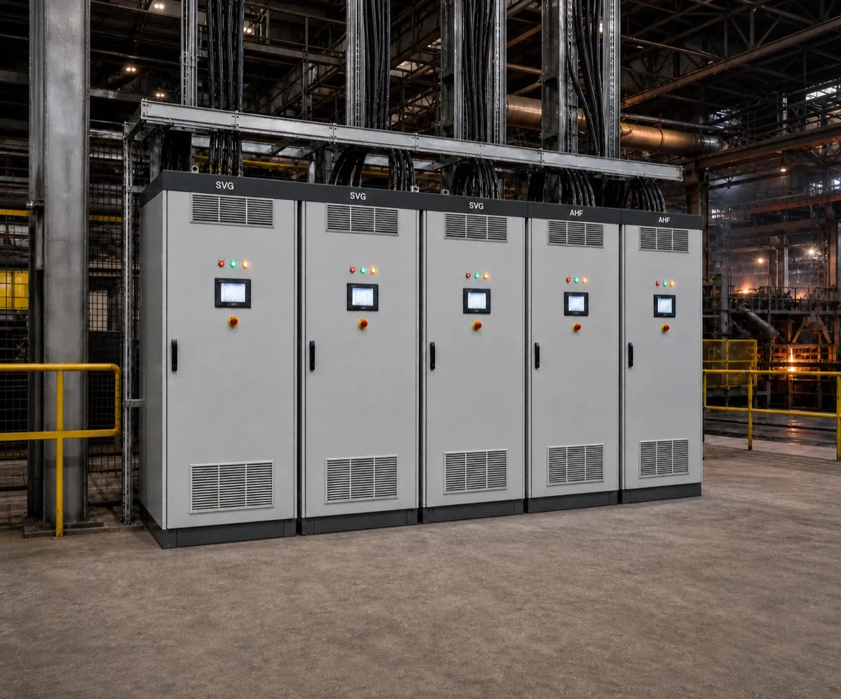
A PV+BESS Reactive Power Compensation Case Study from South Africa
A power factor of 0.98 suddenly dropping to 0.60 is something that immediately gets an engineer's attention.
But what if the system already has a 1000 kvar automatic power factor correction (PFC) system? And what if the PFC simply stops switching when the grid goes offline?
That was exactly the situation we encountered on a PV+BESS (photovoltaic + battery energy storage system) project in South Africa. At first, it looked like a conventional power factor correction problem. After analyzing the operating conditions, however, we found the real issue was more closely related to the transition from grid-connected to islanded operation.
The case reinforced an important lesson: reactive power management in an islanded PV+BESS microgrid may require a different control strategy from conventional grid-connected operation.
The Project at a Glance
The site combines utility power, photovoltaic generation, battery storage, and industrial loads. The key electrical parameters are:
| Parameter | Value |
|---|---|
| Location | South Africa |
| System voltage | 400 V |
| Frequency | 50 Hz |
| Transformer capacity | 2500 kVA |
| Maximum system current | ~3200 A |
| Existing PFC | 1000 kvar |
| Grid-connected PF | ~0.97–0.98 |
| Islanded PF | down to ~0.60 |
Under normal conditions, the system runs in parallel with the utility grid. The existing 1000 kvar PFC operates normally and keeps the power factor around 0.97–0.98. The problem only appears when the utility supply fails.
What Happens When the Grid Goes Offline?
In grid-connected mode, the system can be represented simply as:
Utility grid + PV + BESS → Main AC bus → Industrial loads
When the grid fails, the system changes to:
PV + BESS → PCS → Main AC bus → Industrial loads
The PCS (power conversion system) becomes the key source supporting voltage and frequency in the islanded microgrid. Almost immediately, the measured power factor drops to around 0.60 — a significant change.
But there was another important observation: the existing 1000 kvar PFC did not switch capacitor stages to compensate. That was the first clue that the problem was not simply a lack of capacitor capacity.
Is 1000 kvar Simply Not Enough?
It is the natural first question. The answer is: possibly, but it is not the whole problem.
If the capacitor bank had been operating normally and all stages were already connected, we could simply calculate the additional reactive power required. In this case, however, the PFC did not become the active compensation system after islanding. Two separate questions had to be answered:
How much reactive power does the islanded system actually need?
Why is the conventional PFC no longer responding as expected?
Understanding the Reactive Power Requirement
Taking 400 V and approximately 3200 A as a reference operating point, the apparent power is:
S = √3 × 400 V × 3200 A ÷ 1000 ≈ 2217 kVA
With a power factor of 0.60, the corresponding active power is approximately:
P = 2217 × 0.60 ≈ 1330 kW
The corresponding reactive power is:
Q = √(S² − P²) = √(2217² − 1330²) ≈ 1774 kvar; the project calculation uses ≈1770 kvar as the rounded design value.
So, at this representative operating point, the system requires roughly:
≈ 1.77 Mvar of reactive power
That is a substantial reactive power requirement for an islanded microgrid.
The PCS Can Provide Reactive Power — But Only Part of It
We also discussed the issue with the PCS manufacturer. The PCS already includes reactive power management, but the manufacturer indicated that it can cover only about 20% of this project’s reactive power requirement under the relevant islanded operating conditions:
1770 × 20% ≈ 354 kvar
The PCS could provide roughly 350 kvar of reactive support. The remaining requirement is still approximately:
1770 − 354 = 1416 kvar
This is the key engineering point: the PCS is already helping — it simply cannot supply all the reactive power required by the industrial loads.
Why Didn't the Existing PFC Take Over?
This is where islanded operation differs from conventional grid operation. A traditional PFC controller typically measures voltage and current, determines reactive power or power factor, and switches capacitor stages according to its control logic. That works well in many grid-connected applications.
After islanding, however, the electrical system changes significantly:
The PCS becomes the voltage-forming source.
Power flow can become bidirectional.
The current–voltage phase relationship can change.
The system impedance seen by the loads is different.
Depending on the PFC design, its control logic may also be affected by:
CT polarity and phase relationship
Power-flow direction
Four-quadrant operation
Voltage and frequency limits
Harmonic protection
Measurement location
PCS control characteristics
This does not necessarily mean the PFC is defective. It means a conventional PFC designed primarily for grid-connected operation may not automatically become an effective reactive power controller for an inverter-based islanded microgrid. That distinction matters.
Why Not Just Add More Capacitors?
We considered that approach. Adding more capacitor banks can certainly increase the available reactive power, but an islanded PV+BESS system is a dynamic environment:
The load changes continuously.
PV output changes throughout the day.
The battery can charge or discharge.
The PCS operating point changes.
The reactive power requirement is therefore not constant. A capacitor bank provides compensation in discrete steps, which can lead to:
Too little compensation → PF stays low
Too much compensation → overcompensation / leading PF
Harmonic resonance risk when significant capacitance is added to a system with power-electronic equipment
For these reasons, simply adding another large capacitor bank was not our preferred solution.
Why We Chose SVG
This led us to a different approach: dynamic reactive power compensation with SVG (static var generator). Unlike a conventional capacitor bank, an SVG can continuously adjust its reactive power output to match the actual system requirement. For example:
| Reactive power required | SVG output |
|---|---|
| 400 kvar | ~400 kvar |
| 800 kvar | ~800 kvar |
| 1200 kvar | ~1200 kvar |
The compensation follows the load instead of relying on fixed capacitor steps. For an islanded microgrid with changing load and inverter-based sources, this is a significant advantage.
Sizing the Solution: Why 1600 kvar?
Based on the representative operating point above:
Rounded project reactive power requirement: ≈ 1770 kvar
PCS contribution: ≈ 354 kvar
Remaining requirement: ≈ 1416 kvar
We therefore proposed a ±1600 kvar dynamic SVG. This provides sufficient dynamic compensation capacity for the representative operating condition with an engineering margin above the rounded 1416 kvar requirement.
Importantly, 1600 kvar is the maximum compensation capacity, not a fixed output — the SVG only supplies the reactive power the system actually needs.
A Simple Sizing Reference
Assuming an islanded PF of 0.60 and PCS coverage of ~20%, the remaining reactive power for typical islanded loads is approximately:
| Islanded load (kW) | Remaining reactive power (kvar) |
|---|---|
| 1000 | 1066 |
| 1200 | 1280 |
| 1300 | 1386 |
| 1400 | 1493 |
| 1500 | 1600 |
This explains why a 1600 kvar SVG is a reasonable choice for this project. It is a design reference rather than a universal sizing rule — the final SVG capacity should be determined from the maximum sustained islanded load and the minimum expected power factor.
More Than Just Power Factor Correction
One of the most important benefits of SVG is not the PF number itself — it is the effect on the PCS.
The apparent power of the PCS is determined by:
S = √(P² + Q²)
If the PCS has to supply a large amount of reactive power, its apparent power and current increase. That means part of the PCS capacity is used for reactive power instead of active power.
By installing an SVG close to the main AC bus, much of the reactive power can be supplied locally. The result is:
Less reactive power from the PCS
→ Lower PCS current loading
→ More available PCS capacity for active power
→ Better utilization of the PV+BESS system
This is particularly valuable when the system operates independently from the utility grid.
Recommended Operating Strategy
We do not recommend treating the existing PFC and the new SVG as competing systems. Instead, they should have different roles:
Grid-connected: Utility + PV + BESS. The existing 1000 kvar PFC continues to provide conventional reactive power compensation.
Islanded: PV + BESS → PCS → Main AC bus. The PCS provides reactive support within its available capability; the 1600 kvar SVG provides the remaining dynamic reactive power.
This creates a complementary control strategy: PCS + SVG = coordinated reactive power management.
Recommended System Configuration
A simplified architecture for the site:
| System connection | Function |
|---|---|
| Utility Grid → Transformer → ATS → Main AC Bus | Grid-connected supply path |
| PV + BESS → PCS → Main AC Bus | Inverter-based supply path |
| Main AC Bus → Industrial Loads | Load supply |
| Main AC Bus → PFC (1000 kvar) | Grid-connected reactive power compensation |
| Main AC Bus → SVG (±1600 kvar) | Dynamic reactive power compensation |
For this application, we recommend a bidirectional SVG (e.g. ±1600 kvar) so the system can both supply and absorb reactive power as operating conditions change.
What About the Existing 1000 kvar PFC?
We do not necessarily recommend removing it. The PFC already works well during grid-connected operation. A more practical approach is to coordinate the two systems according to the operating mode:
Grid ON → PFC operates normally.
Grid OFF → SVG becomes the primary dynamic reactive compensation device.
The operating mode can be coordinated through the ATS or the PCS grid/island status signal. If the PFC is required to operate during islanding, its control and measurement conditions should first be verified, including:
CT direction
Voltage measurement
Phase sequence
Four-quadrant operation
Reverse-power conditions
Harmonic protection
Control interaction with the PCS
The objective is not to force the capacitor bank to switch. The objective is to keep the entire microgrid stable.
An Important Engineering Lesson
This project reinforced one key point:
A microgrid is not simply a traditional grid with solar panels and batteries added to it. When the utility grid disappears, the entire electrical environment changes — the source, the control strategy, the power-flow conditions — while the reactive power requirement of the loads remains.
Reactive power compensation therefore needs to be designed as part of the overall microgrid architecture. A PFC system may be sufficient for conventional grid-connected operation. For dynamic islanded operation, fast and continuously adjustable reactive power compensation can become far more important.
Final Solution
For this South African PV+BESS project, Sinava Power proposed:
±1600 kvar Dynamic SVG
The operating philosophy is:
Grid-connected: 1000 kvar PFC → conventional reactive power compensation.
Islanded: PCS → PV/BESS power conversion + available reactive support; SVG → dynamic compensation of the remaining reactive power.
This approach addresses the problem at the system level rather than simply adding more capacitor stages.
Conclusion
A power factor dropping from 0.98 to 0.60 after islanding may initially look like a simple capacitor compensation problem. In a PV+BESS microgrid, the underlying issue can be far more complex.
In this South African project, the PCS could provide only part of the required reactive power, while the existing PFC did not function as the main compensation system after the transition to islanded operation. Our solution was to introduce a 1600 kvar dynamic SVG and coordinate it with the existing PFC and PCS. The objective was not simply to improve the PF number — it was to create a more stable reactive power environment, reduce the reactive burden on the PCS, and improve the overall utilization and stability of the islanded PV+BESS system.
For modern PV+BESS microgrids, reactive power compensation should be designed together with the power conversion system — not treated as an afterthought.
Sinava Power — Power Quality Solutions for Modern Energy Systems
Frequently Asked Questions
Q1. Why does power factor drop so much when a PV+BESS microgrid islands?
When the utility grid is disconnected, the PCS becomes the key source supporting voltage and frequency. System impedance, the current–voltage phase relationship, and power-flow direction can change. The loads remain, but the previous reactive-power balance may no longer hold; in this project, the measured PF dropped from about 0.98 to 0.60.
Q2. Why might a conventional PFC bank stop compensating after islanding?
A conventional PFC may be configured around grid-connected voltage, current, CT polarity, and power-flow references. In islanded mode the source is inverter-based and power flow may be bidirectional, so its measurement or control conditions may no longer be valid. In this project, the PFC stopped switching capacitor stages; the exact cause should be confirmed from controller settings, alarms, wiring, and measured waveforms.
Q3. Why is SVG more suitable than adding more capacitors for an islanded microgrid?
A capacitor bank provides reactive power in discrete steps, which leads to under- or over-compensation in a dynamic load environment and can introduce harmonic resonance. An SVG provides continuous, fast, bidirectional reactive power that follows the actual load, making it a better match for an inverter-based microgrid.
Q4. How is the required SVG capacity sized for an islanded PV+BESS system?
A practical reference is: calculate the reactive power at the lowest expected islanded power factor (Q = √(S² − P²)), subtract the verified reactive contribution available from the PCS, and add an appropriate design margin. In this South African case, the manufacturer indicated about 20% PCS support; using the project’s rounded values gives 1770 − 354 = 1416 kvar, leading to a ±1600 kvar SVG selection.
Q5. Can the existing PFC and the new SVG coexist in the same microgrid?
Yes. The recommended strategy is: PFC handles grid-connected compensation, SVG handles islanded dynamic compensation, with the operating mode coordinated through the ATS or the PCS grid/island status signal. The PFC's CT direction, phase sequence, four-quadrant behavior, and harmonic protection should be re-verified for islanded operation if it is to participate.
About Sinava Power: Sinava Power provides power-quality solutions for modern energy systems, including SVG (static var generators), AHF (active harmonic filters), and power-monitoring devices for industrial, renewable and microgrid projects worldwide.
Contact our engineering team | Explore Sinava Power SVG solutions